Background
Visualizing the break-up of Titanic is easier if we look at a map of all the major pieces. From that, it becomes easier to construct a map of the forces needed to create the pieces. Finally we may derive the entire break-up process.
The following figures layout a deck-by-deck look at the major pieces derived from what was discovered in my Woods Hole research and the tidbits of evidence gleaned from TV shows and talks with wreck observers. The major pieces are shown in different colors. On all the drawings, the red dotted lines show the extent of the missing keel sections to help the viewer understand the relationship of that to higher decks.
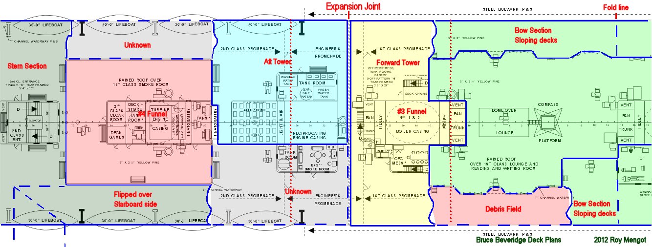
The Boat Deck
The Boat Deck and A-deck were superstructure. They were composed of 1/4" (6mm) deck and wall plating and their construction was kept as independent from the structural hull as possible. Both decks contribute little to the break-up process and mainly reacted to what was happening on the strength deck, B-deck, and below. Both decks also have a natural division at the expansion joint. The decks physically stop there and only a pair of sliding brass plates cover the gap. This allows the superstructure to bend and sway slightly in a heavy sea, and not put unneeded strains on the deckhouses. When Titanic bent such that the stern dropped nearly level in the water, A-Deck and the Boat Deck now had a longer radius to cover than B-deck, which was the axis of the bend. Since steel doesn't stretch, the two decks violently created new expansion joints at widely different points.
The Boat Deck starts to define the principle pieces of the wreck.
The bow section and its sloping decks in the tear area have only two segments of boat deck going down to the tear from #2 funnel. Some of the sloping deck on the port side remains however a segment of Boat Deck was pictured in National Geographic and captioned as "Unidentified deck wreckage". I recall from the Woods Hole footage that the port side seemed to be there but the starboard side was too fuzzy to tell. The wreckage pictured in the NatGeo debris definitely came from one side of the 1st Class lounge or the other.
The "Forward Tower", so called because it comprised several decks clustered around the central uptake and sat on the bottom like a big tower when compared to surrounding debris. Of note, the vent shafts and fidleys at the fore end of the #3 funnel uptake form a honeycomb of steel plates. We shall see that this arrangement makes the front of the uptake a strong natural boundary for the tower. The boat deck through C-deck all broke along the same edge and, strangely, at similar points on the aft edge of the fidley shaft. Watch for this in lower decks. Otherwise, the boat deck broke away from the 1st Class Lounge wall and across the narrow points at the sides.
Aft of the expansion joint, a new dynamic begins. The Aft Tower Only includes the port side of the Boat Deck and the deckhouse for the engine room uptake. That deckhouse contained water tanks and a small lounge for the engineers. The starboard wall of the uptake forms the starboard boundary of the towers as all of the starboard decks on B - D Decks behaved differently. What happened to that section of the Boat Deck is unknown.
Along side the 1st Class smoke Room, the port side broke at the aft end and the starboard side broke near the fore end. The whereabouts of the portside piece is unknown, possibly still attached to the Aft Tower. The starboard side was flipped up and twisted over the side of the stern. It was still hanging there as late as 2000. It's very prominent of the wreck model.
The roof of the 1st Class Smoke Room and deckhouse for the 4th funnel were pulled off the wreck during the breakup. The base of #4 funnel sits by itself in the debris field.
A-Deck
A Deck has a mix of similarities and differences to what happened on the Boat Deck.
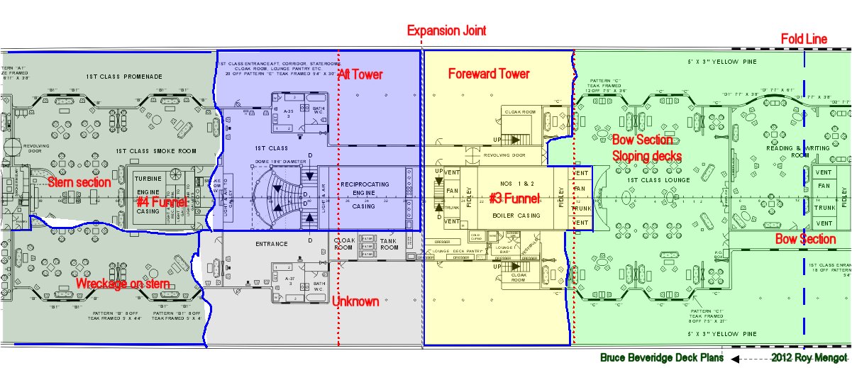
The full width of A-Deck slopes down from #2 funnel to the tear and it tore around the uptake less evenly than other decks. The lounge roof stayed anchored to #2 funnel resulted in the lounge walls being torn apart. This can be seen on the model. The Forward Tower therefore is bounded by the sides and expansion joint gap aft. Some of the promenade weather covers are supposedly still attached to the tower between A-Deck and the Boat deck.
At the second tower, we see the Boat Deck pattern of the port side and uptake being there, but something else happened on the starboard side. The aft boundary of the Aft Tower is only generally indicated. Its precise edges must come out of the unreleased 2010 data. The starboard side may have been broken off as a separate piece. We'll see that B and C-Decks in the same area peeled back and settle over the stern. Past of the missing section may side twisted under B and C-decks.
Otherwise the center and port thirds of A-deck on the stern seems to be there, but the starboard third seems to be shattered and difficult to sort out from other debris.
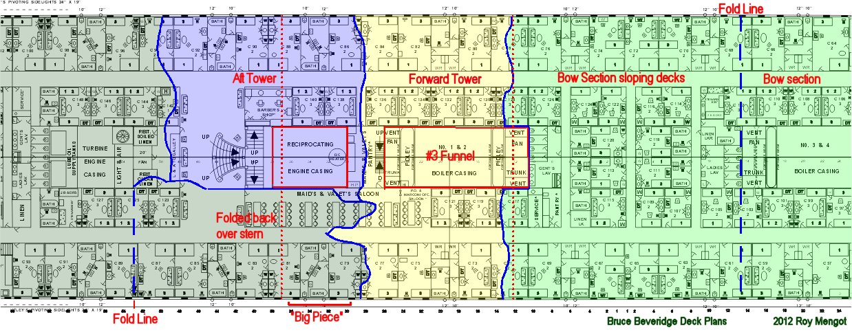
B-Deck
Things start to get interesting on B-Deck. B-Deck is the strength deck. It is designed to balance out the double bottom for tension and compression stress in a heavy sea. The yellow strips indicate the double 1" (25mm) outer plates (darker yellow) and the single 1" plates outboard and along the funnel uptakes that form the major strength elements to the deck. The deck plates between the yellow strakes were also heavier stock than decks below it.
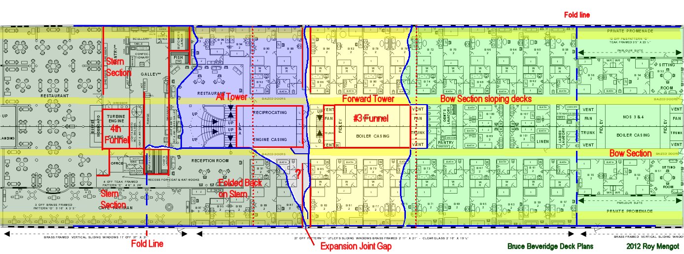
B Deck folds down from #2 funnel and breaks around the honeycomb of vent trunks before cracking out to the sides. Both sides of the bow section were still attached to B-Deck along its full length, which created that swooping deck and shell plate canopy that are seen on the model and the Ken Marschall paintings. Those connections appear to given way in recent years, significantly altering the appearance of the tear area.
B-Deck forms the sides of the Forward Tower and, with the strong uptake construction, give the tower much of it's shape. The broken aft edge of the tower is more problematic. The expansion joint has no construct at all on B-deck itself. A person walking the hall would see two doors that open to a long steel-walled corridor that dead-ends in a leather covered gap in the outer wall. Overhead in A-deck are the overlapping brass plates. While the superstructure deckhouses at B-deck and above are not supposed to effect B-Deck, they do stiffen each side of B-deck enough to where various stresses can manifest themselves in the expansion gap corridor. That appears as slighter hotter spots in simulations such as the Gibbs and Cox or the Stettler and Thomas mentioned elsewhere. The short of it is that cracks can appear in the region of the expansion joint and B-Deck appears to have broken though this area. The 2010 data should pinpoint the break-line.
The Aft Tower is the same scenario as per the decks above. We know that large chucks of starboard B and C Decks folded back onto the stern section. These sections fit very nicely with the boundaries of the two towers. On the model, I had to build the B-deck section separately to make it peak out from under C-deck the way it did in the Woods Hole imagery. The fact that B-deck is stiffer with those doubled and extra heavy plates may have caused it to break the peeled back section somewhere in between when the stern impacted. B-deck Flipping back may have caused A-deck to tear apart as well. Consult the model in the Stern Section portion of this website.
What gets interesting is that Forward Tower is the full width of the ship. But the Aft Tower takes off the port 2/3rds of the ship for several decks and leaves the starboard decks to flap in the current. What were the sides of the ships doing this part of the break-up process?
Another interesting thing is that #3 funnel uptake sticks out from the Forward Tower and left very uniform 6' (2 meter) notches in B,C, and D-decks. The notch is also on A-deck, but broken differently. Why? For that matter, why didn't the decks break at the corners of the uptake as steel is apt to do? The answer is in the original construction plans from H&W. This answer may solve other questions on B and C-Decks and the whole break-up process.
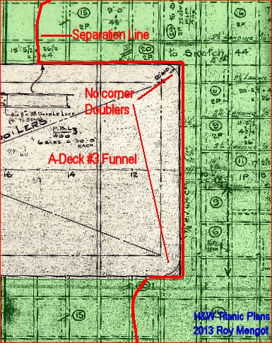
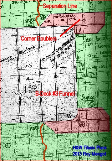
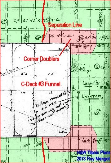
What the plans show is that to prevent cracks from radiating from the corners of the major openings, trapezoidal shaped doublers were added at the corners of all large openings including the stack uptakes, stairwells, etc. Doubling is called a "crack arrester". When a crack reaches a doubled plate, it can't jump to both plates and tends to stop. Doublers in these areas are a common naval architecture construction technique. What's different is that the doublers are use on all decks of the structural hull from B-Deck on down, but A-Deck is superstructure so it didn't have the doubler plates. It was along for the ride of whatever the strength deck below decided to do and broke as it wanted.
Remember this for the discussions about the Aft Tower section.
The really interesting thing has to do with the "?" mark on the diagram. If the B-Deck sections back on the stern do match the break on the map, then B-deck broke along the line aft of the "?", rather than the line in front of it going down the expansion joint corridor. That would cause the strength deck to form a 'hook' that might have caused the Aft Tower to start being pulled to port if forces were pulling B-Deck slightly to port. Here's where the doublers around the uptake openings may also play a part. It's possible the doublers helped form that hook. If confirmed, this would pose the most interesting dynamic of the break-up process. C-deck right under this spot appears to have broken in a very convoluted way. This one area, at both the stern peeled back decks and on the tower debris, should have a high priority for review and accurate mapping.
Yet another interesting thing is the aft edge of the Aft Tower breaks off somewhere around the galley area for the 1st Class restaurant. The break-line drawn is a guess at best. What makes that part of the ship interesting is that most of the galley walls are steel walls to better contain heat, smells, fires, spills, or whatever may happen in kitchens. Most other walls in cabin areas are wood. We'll see this again on lower decks. These deckhouse like structures (highlighted in red on all the drawings) do seem to effect or at least guide some of the breaking process.
The rest of B-deck on the stern was relatively intact except it collapsed unevenly of the pillar system with C-deck below. All of that has since collapsed fully down to D-deck.
C-Deck
C-Deck is the second strongest deck and intended to assist B-Deck in providing that upper-deck balance to the double bottom. To a naval architect, that's called creating the ship's girder, or treating the ship as an I-beam when giving the design its strength. C-Deck also has a 1" outer deck stake and all decks will have a somewhat heavier strake down the edges of the uptakes and stair openings.
C-deck again has full width deck sloping down to the tear. Again we see the tear around the uptake then radiating off the uptake to the sides beginning at the aft side of the fan trunk, due to the doublers, to form the forward edge of the Forward Tower section. The aft edge of the Forward Tower is less certain and will require study of the 2010 data. The broken end of C-Deck flipped back on the stern has a severely jagged edge. It doesn't match the broken edge of B-deck above. There is reason to believe that the doublers on the uptake corners may have helped to shape this area.
It was obvious while building the wreck model that the peeled C-Deck section had to extend well into the Maid's and Valet's Dining Room but the relation to the broken B-Deck section under it wasn't obvious. The port side tower now adds context that these two decks were working in tandem, possibly with the sheer strake to form their own dynamic as other forces jerked the Aft Tower to port. A-Deck was along for the ride and D-deck below behaved differently again.
The location of the "Big Piece" is also shown. The cabins there on C-deck are now lying well back on the stern section from that section of deck flipping back.
D-Deck
D Deck follows the break pattern up forward as it slopes down from #2 funnel to the tear and is probably part of the Forward Tower section. Aft of that things start to change.
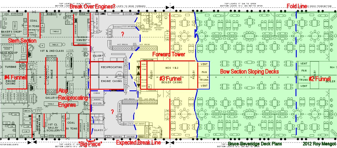
The after side of the normal Forward Tower break line is more uncertain and bears detailed scrutiny in the 2010 data. One issue is that D-Deck appears to be broken off along the forward edge of the remaining engine cylinders on the stern. That line happens to coincide with steel bulkheads in the 1st and 2nd Class Galley. It also coincides with what might be damaged in the keel broke inward and drove those two forward cylinders into D-Deck right above.
The 'Expected Break Line' line corresponds to the normal line of where decks above are roughly broken to form the forward tower. Something else may have happened. If D-Deck is broken back over the engines then the starboard area between the engines and tower is a mystery. It's not yet know if it stayed with the tower, or broke separately, and where. It didn't flip up over the stern as B and C Decks did. On the port side, it's still unknown if the Aft Tower includes a section of D-Deck or not. So that area is in question as well.
From the reciprocating engine room on back, D-Deck is generally intact until the aft well deck, where some implosion damage can be seen starboard and outboard of the cargo holds.
Of note, when building the wreck model of the stern, I had to put a hump in C-Deck over the galley area to make other landmarks on the stern line-up. Looking at the plans, the galley has a large number of steel walls that drove the shape of the stern. As we saw with the 1st Class restaurant galley, these steel walls once again seem to have had an impact on how the break-up progressed. This may have impacted how and whether D-Deck is part of the Aft Tower on the port side.
The bottom portion of the "Big Piece", often called "The Little Big Piece", is also shown. It's interesting that the shell plate fragment sticking down off the "Big Piece" coincides with where D-Deck falls into question. Another big large chunk of shell plate called the "Ballard Piece" starts just aft of, and runs below the Big Piece". This becomes a major question for the 2010 data.
E-Deck
An entirely new dynamic comes into play as E and F-Decks combine to form a new wreckage section called the "Galley Decks", so called because F-deck housed the Galley for the 3rd Class dining room and for the third time now galley related fixtures had an effect on the shape of the wreck.
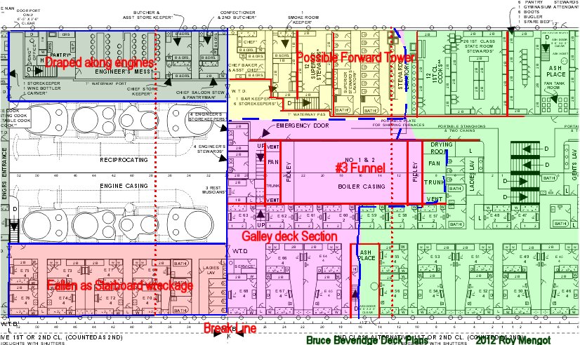
This section was identified already in 1986 but never fully documented to determine its size and significance until 2010. The forward boundary is still unclear to me for the center-port side, pending examination of 2010 video. The fact that it exists becomes more evident when we examine F-Deck. E-Deck does feature structural differences from the decks above it. First, the funnel uptake lengthens as the stack is split going down to #1 and #2 boiler rooms. E-Deck has a number of steel walls down the port side that housed crew members. The stewards referred to them as "Glory Holes".
The aft wall is watertight bulkhead K. This left the two sections of E-deck on either side of the engines to fall off of lie draped on the side of the engines. Interaction of the steel walls with the Forward Tower may have left portions of E-deck broken off and still part of the Tower. That is yet to determine.
The forward starboard edge is broken along frame 16 aft almost directly above the walls for the coal bunkers below. Both E and F-Decks are broken on that line.
The section of Forward Tower shown is only a wild guess. The E-Deck plating itself is likely still part of the galley section. The TV imagery in "Titanic at 100" of this was notional on the part of the animator so this map will need to be amended after study of the 2010 data.
The reason the Galley Deck Section may have separated from the Forward Tower section above has to do with the shape of the uptake. On the Profile View, we see that the uptake slopes on E-deck and that may have carried stresses differently.
Another interesting point is that the port side shell plate has horizontal splits at about the E and F-Deck levels that led to that shell plate canopy seen on the model of the bow section and in 1986 Woods Hole imagery of the bow. This difference from the starboard shell plate may indicate that the Galley Deck section broke at its forward end early in the break-up. If the shell plate deformed and bowed or bulged outward as a result of the keel failure, separation of the sides from the decks would happen first at right about where the Galley Deck section is situated. The aft edges are just the partial E and F-Decks in the engine compartment.
Aft of the engine room, E-deck on the Stern Section is generally intact until the aft well deck area.
F-Deck
F Deck has a very different geometry to the ##3 funnel uptake than E-deck. The additional steel walls for the various kitchen rooms, and the likelihood that watertight bulkhead 'H' is also part of it, provide a solid framework and explanation as to why these two deck sections stayed together. It's worth noting that the watertight bulkheads were built up on each deck. The deck plating was done first, and the bulkhead was placed second. This allowed a bulkhead section to be moved a little or shaped to solve a space usage problem. Where the bulkhead to not directly aligned with the bulkhead on the deck below, any deck sections in the offset area were caulked to maintain the water tight integrity.
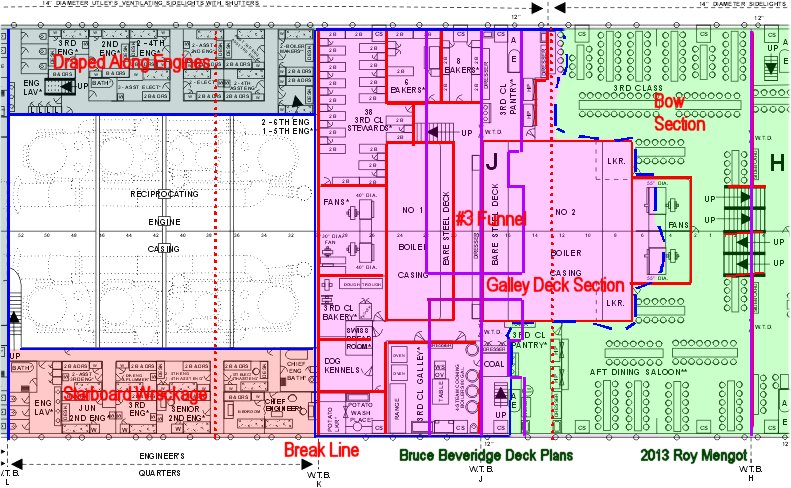
A look at F-deck aft of the #2 funnel makes it clear why this 'Galley Deck' section would form. The uptake casing becomes very broad and is heavily supported by a large number of additional steel walls for the galley. Not all of these walls are highlighted in red.
The purple lines are for the Coal Bunker section immediately under the Galley Deck section. These are added to show how the vertical steel structure of that section may have interacted with the Galley Deck section.
The partial deck portions of F-Deck in the engine room are wreckage but, again, F-deck is generally intact on the stern section until the bend in the stern near the aft well deck.
G-Deck
G Deck is little more than a shelf of varying widths around the machine spaces but it gives form to the next player in the break-up story, namely the coal bunker assembly for boiler rooms 1 and 2.
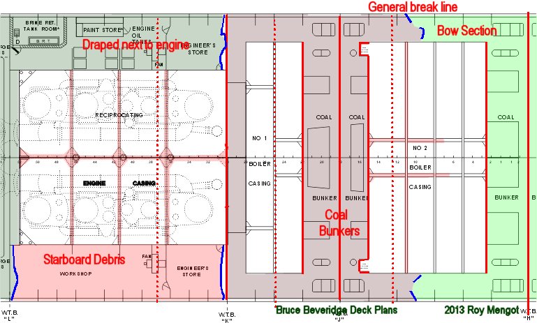
G-deck appears deceptively sparse. The sections on each side of the reciprocating engines are broken off at watertight bulkhead K and are either alongside the engines or or just off in the debris.
The center shelf around the boiler rooms and floor top to the bunkers is small in area. WTB J combines with the coal bunker walls to form another honeycomb of steel boxes like we see in the in the uptakes and the galley areas. The bunker walls extend from the Tank Top to F-deck above. The walls are .30" (7.6mm) and thicker going down. Reenforcement inside the bunkers along the watertight bulkhead includes 20" and 36" I-beams and 10" C-beams. G-Deck forms lateral and longitudinal support for this structure. The coal bunker itself is slit by a firemen's passage offset to starboard so the coal bunkers are composed of two rectangular sections, joined at the top, with the bulkhead down the middle.
All of this is right under the honeycomb of galley walls that give the Galley Deck section its form. Note also that the bunkers sit squarely on the center of the forward broken keel section. WTB K at the engine compartment is largely a bare wall upto and passing G-deck. WTB H is likewise a strong honeycomb of rectangular boxes extending to the forward end of the Galley Deck Section but remains firmly in place deep in the bow section.
In the Woods Hole video from 1985, a film clip from the submersible began at a large object nearly central between the bow and stern sections. My thought at the time was "coal bunker" because it was obviously large, had long fingers of heavy steel beams, and a vertical ladder on it. It was called an unknown navigation hazard on a 1992 expedition. The coal bunker on the forward keel section is gone as the keel section lies inverted on the ocean floor. I'll contend the coal bunkers broke off relatively intact and remain to be further documented. They didn't just break-up into little pieces.
The Tank Top
The Tank Top consists of the two keel sections documented in 2005, the Coal Bunkers section, and the base for the bow and stern sections. The double bottom is formed by the outer 1" (25mm) shell plate and the Tank Top, which was about half as thick. In all engine and boiler spaces there is an additional raised working floor above the tank top but this is generally not shown. The double bottom is 5'3" (1.6m) thick over its length except under the reciprocating engines where it thickens to 75" (1.9m). Within the double bottom are bilge tanks and ballast tanks to service and balance the ship.
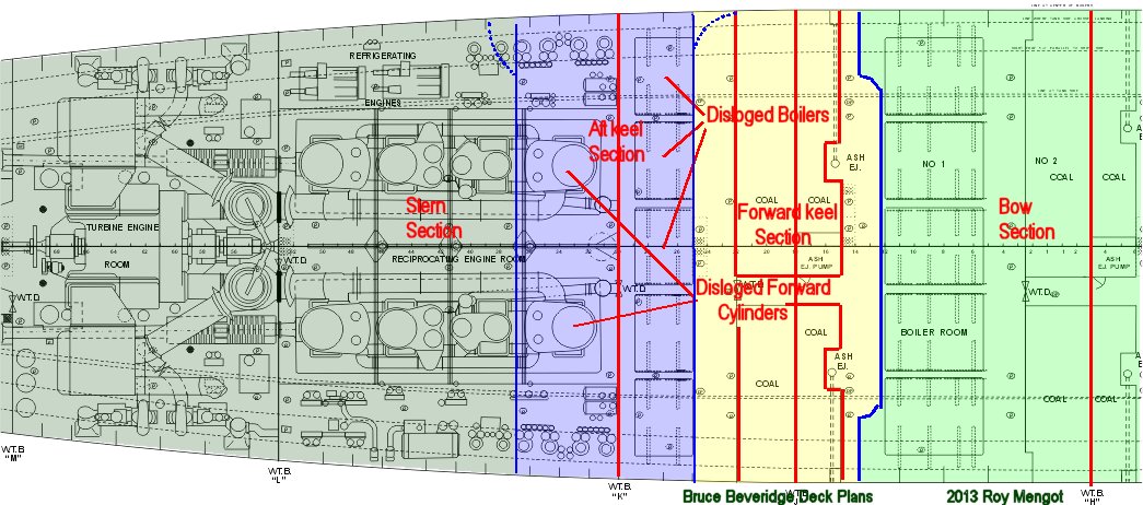
The broken keel has a few non-straight edges resulting from the manner of fracture, but the Tank Top fractured more linearly along frame lines except for a couple of jogs.
The Aft Keel Section included the forward part of the engine bed plates, the forward low pressure cylinders of the engines, bulkhead K, and the 5 single ended boilers from boiler room 1.The engine bed plate remains attached to the keel section as it lies inverted on the ocean floor. All of the other items are scattered in the debris field.
The Forward Keel Section held only the Coal Bunker Section. The heavy steel walls and construction, plus the likelihood that at least the two halves of the bunker survived as units, warrant elevating the bunkers to an identifiable section. These sections also have diagonal support in the form of the ash ejector recesses built into the bunker walls and longitudinal beams inside the bunkers. Refer to some of the bunker construction details mentioned for G-deck above.
Profile View
This profile map of the broken middle portion of Titanic helps to identify the major internal pieces of the puzzle in vertical space. It's particularly useful in mapping the energies needed to create the pieces. Red lines are added to highlight where some of the major steel walls found on the decks and other structures are located in side view.
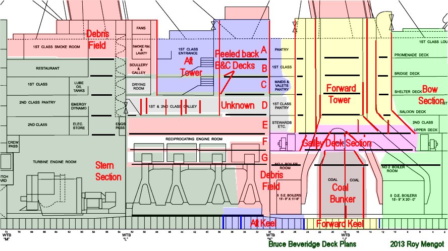
A pattern starts to emerge from seeing all the sections in proximity to each other on the ship. The Forward Keel Section, the Coal Bunker Section, the Galley Deck Section, and the Forward Tower all form a column of steel through the uptakes. A number of steel boxes and honeycombs are oriented vertically. If the keel buckled and the two keel sections were forced upward slightly, the entire stack would likely move in unison.
A sudden shortening of the keel caused when the keel bucked would have different effects. Elements atop the after keel section would be dislodged if the Aft feel Section were forced up and we find all of those elements scattered in the debris field. With the upper shell plate forming a temporary "hinge" as the stern fell back to water, small portions of D-Deck and the partial decks below would buckle for a few feet.
Dislodging the Aft Tower and freeing B and C-decks to fold back on the stern would receive energy to do so from the action of the shell plate sides during the break-up process.
The Sides
What's missing from this map of the broken middle portion of Titanic are the side plates. The critical driver to to understanding how the energies of the break-up propagated to create the pieces can only be fully explored and explained when the 2010 data on the nature of shell plate sections becomes available.
Copyright 2012 Roy Mengot