The Titanic broke apart from the bottom up, mainly.
Background
The break-up story has a bit of history to it that is useful to understand. Much of the conjecture about whether it broke at all comes from testimony of passengers at the American hearings. The American Inquiry was more open and interested in finding out what basically happened. The Board of Trade (BoT) hearing in the UK was different. The BoT hearing was mainly interested in what procedures were followed by the crew and builders as they pertained to shipping regulations and the disaster. No passenger testimony was solicited. There is the appearance of a cover-up to mute any claims that ship broke apart at all. The BoT was partly on trial itself for what regulations were in place. It was enough trouble to sort out the matter of a major maritime disaster. Any further discussion about ships breaking would only put the regulations themselves further on trial. The final report stated that Titanic sank intact. And so it lay until discovered in two pieces in 1985-86.
One of the last big technical questions about the sinking is about *how* Titanic broke apart. We have a picture of how the ship behaved from the testimony of survivors who claimed Titanic did break. A general consensus of those passengers was that Titanic was tipped up, there were explosions and explosions underwater and the stern righted itself momentarily. When steel breaks, it makes a loud noise. Rivets popping can sound like gunshots. The stern then quickly tipped forward again and hung there for a period of 5 minutes or less. After that, it too slipped beneath the waves.
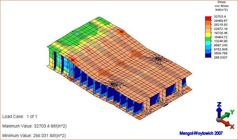
The forensic studies since 1985 also have a history. Among the first attempts to understand the forces at work in Titanic's predicament was the Finite Element Stress Analysis simulation by Gibb's and Cox personnel in 1996. (See Figure 2 below) The simulation showed extreme tension stress in the region spanning the 3rd funnel and corresponding compression stress in the engine room area. It also showed "hot spots" at the expansion joint. While it was not stated as such in the study, the basic conjecture was that the breakup started at the expansion joint and went top-down. In was discovered in later years that the modeling of the hull did not have the benefit of more recent access to the construction plans. As a result, the computer model did not accurately reflect Titanic's construction and the 'hot spots' in the expansion joint areas were highly exaggerated. More recent modeling by Stettler and Thomas confirms and refines the stress levels of the 1996 work but still does not point to a definitive failure point. Both the keel and strength deck areas were in the failure zone of stress and the remaining question is "Which gave first?"
James Cameron in his 1997 epic film "Titanic"
led us to believe that Titanic cracked at the top behind the 3rd funnel
at the expansion joint and tore down through the decks, leaving the double
bottom to pull down the stern section. At the time, that was the best thinking
available on the break-up and was popular conjecture. In a more recent 2012
program "Titanic: The Final Word", he used the analogy
of a breaking a banana with the peel acting as the double bottom to pull
down the stern. Even James Cameron backed away from that example and talks
about a more asymmetric top-down break forward of the 3rd funnel that was
animated at the end of "Titanic: The final Word".
With this in mind, a forensic analysis has to meet certain rules:
1. The break-up process has to sink the stern. Any clean break through the ship will leave the stern floating as it's own ship, or at worst, restart a flooding and sinking sequence that could take much longer than mere minutes. That didn't happen.
2. The keel did not behave like 5 feet of shoe leather. The cellular double bottom is designed to be rigid and therefore was brittle. The piece part construction and lap joints used were fine for handling the compression and tension stresses of normal service, but are weakest in handling the extreme tension stresses of Titanic's predicament. Bending the keel destroys whatever strength was there like bending corrugated cardboard across the grain. It could never "pull down the stern" after bending a few degrees, never mind the 10+ degrees of bend needed to allow the stern to nearly right itself. If the ship broke down to the double bottom, then we are asking the damaged double bottom to do what the entire intact ship's structure could not. That didn't happen
3. Once you've accounted for all the pieces, you have to account for the forces that made them pieces. Steel doesn't just come apart. There has to be a force or major stress that breaks steel. This is where top-down scenarios are weakest. Once the stress of the tipped-up predicament breaks the ship top-down, all the stress and energy required to break other portions off the ship are gone. Steel structures do not flake off or pop off in the current during descent. A 25 knot current won't break steel, especially if the ship keeps adjusting itself to an attitude of least resistance. Parts cannot be throw off by centrifugal force from a rotating stern section as it will never spin fast enough. Gravity is neutralized if both the main part and the loose part are already falling together. Fanciful TV animations that have steel structures popping and flinging off the stern in the water column don't reflect reality.
4. The process has to leave the wreck the way we find it today. We're looking for consensus among forensic experts of what did happen.
Breaking Things: 101
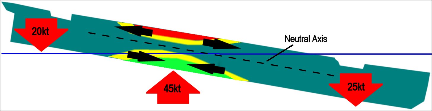
The forces available to break the ship are the flooded bow pitted against the weight of the stern while sitting on a fulcrum of buoyancy in the center of the ship. If we think of the ship as a beam, or a box girder, then the forces available to break the steel structures are the tension stress (pull stress at the top) or the compression stress (push stress at the bottom). The neutral axis is the point between them where tension and compression cancel each other out.
The major problem with any top-down break theory is that it violates Rule 1 above. If Titanic broke straight down at the expansion joint, all the major tension on the ship is released. Where do you get the energy to break it cleanly again in front of the 3rd funnel? That's the clean break we see on the wreck. Likewise, if it broke in front of the 3rd funnel, again, where do you get the energy to create the pieces we find aft of the 3rd funnel? Either way, these theories violate rule #2. Assuming the break stops at the double bottom, bending the double bottom destroys it and that would leave the stern afloat as it's own boat, which violates rule #1 again.
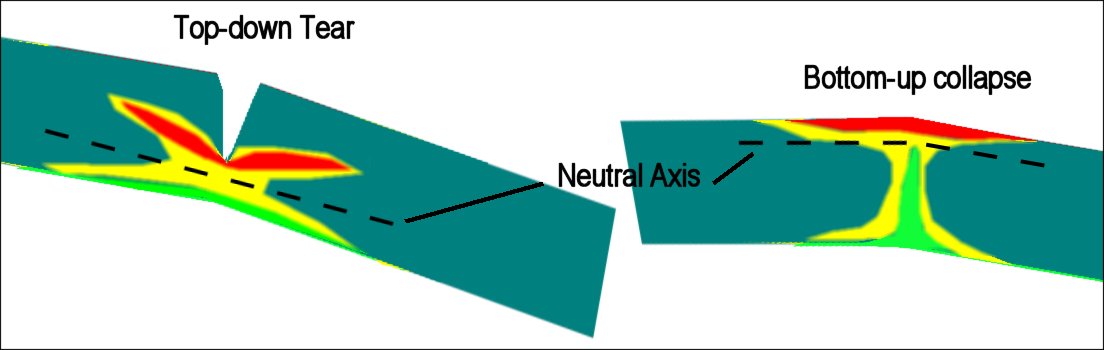
Compression stress in a structure like a box beam or truss girder always has the advantage. In compression, the steel doesn't have to break, it only has to bend. At that point, the bottom can no longer hold a balance against the tension at the top and it fails. That leaves the compression stress to fall to the element above the bottom and the neutral axis raises. The elements above can do no better, they fail, and the neutral axis continues to rise until all the stress is left at the topmost piece. As the neutral axis rises, those structure behind it have the opportunity to fail through the bending or jamming together of components that are still connected or butting together is already broken. Steel can bend to a degree along a straight axis but as cracks start, they will propagate into a fracture of the steel.
In a tension break, there is enough compression resistance in the mass below to neutral axis to allow the tension stress to break the steel by pulling it apart. In that case, the neutral axis falls are the tear works it's way down. In this case, the stresses on all materials above the falling neutral axis have all of the stress relieved. Steel doesn't stretch so there is little opportunity for further damage though collisions or further cracking and tearing.
An asymmetric (non-symmetric) break-up implies both sides of the ship did not behave the same way, or that a tear started in one corner and ran laterally along the deck and down the side simultaneously. Titanic did have a list of upwards of 10 degrees to port at the moment of break-up. Most of the starboard shell plate on the stern section came off near the surface, but most of the port side shell plate is still attached to the strength deck, B-deck, on the wreck. With the ship slightly tilted, a twisting action has to be considered between the bow and stern areas. Even so, if the basic direction of a tear was from the top down going diagonally, the neutral axis would still follow the tear and relieve stress behind it.
The only other forces available that can tear steel structures are implosion forces, where high water pressures (where water pressure crushes air filled spaces), or impact forces. Pieces broken off at impact will be lying next to each other on the bottom. Implosion damage on Titanic's stern appears limited to the after well deck area, where the last three narrow compartments were pulled under before they could completely flood. All the other more open area would flood fully before any trapped air would be a factor. Wooden cabin walls are swept away long before the stresses that could threaten the steel materialize. The current passing the wreck sections as they fell would take away most loosely attached items but would not provide stresses that would threaten to break steel structures.
The current engineering and physical evidence doesn't support most of the fanciful animations seen through the years. It appears today that the cause of the break-up occurred bottom-up, resulting from the buckling of the keel. But the break wasn't evenly symmetrical either. The port and starboard sides propagated the initial break differently leaving the port and starboard sides to behave differently. When a full mapping all the hull sections is released from the new 2010 data, a clearer picture will emerge of how an initial failure propagated.
A detailed map of the tear helps us visualize the composition of the major sections of the ship between the bow and stern sections and how those pieces fit together.
A bottom-up break
As a preface, consider breaking a stick and a structure like a cardboard tube. The solid stick will break top-down. The cardboard tube will collapse on the bottom and bulge the sides outward before it tears. The Titanic has more in common with the tube than a stick.
I'll reference several older 1997 works featured on the television special "Titanic: Anatomy of a Disaster". One is the finite element simulation of stresses to Titanic's hull during the sinking done by naval engineers at Gibbs & Cox, Inc. The other is the Hacket/Bedford paper "The Sinking of Titanic - Investigated by Modern Methods" published for the Royal Institute of Naval Architects by a then current and retired naval architect for Harland & Wolff (builders of Titanic). These are supplemented with the paper I co-authored with Richard Woytowich for the Society of Naval Architects and Marine Engineers (SNAME) titled "The Break-up of Titanic, A Progress Report from the MFP", the 2012 paper "Flooding and Structural Forensic Analysis of the Sinking of the RMS Titanic" by J.W. Stettler (M), B.S. Thomas (M), and my own research at the Woods Hole Oceanographic Institution archives on Titanic.
The evidence driving this discussion is the current condition of the stern. Of note, the starboard shell plate is missing for some 160 feet (42 meters) aft of the forward tear. The debris alongside the wreck is a mix of decks and shell plate sections that comprise a fraction of the original mass. This huge section fell off at the surface or sometime well before impact. The port side shell plate of the stern is still present and attached along B-Deck (the strength deck), but is separated from the keel for upwards of 120 feet (36 meters) or more aft of the tear. It is splayed out too far to have "bounced" out there on impact. The ship's lower structure of the keel, the watertight bulkheads, the decks between them, and the interior pillar system also make for a strong structure. This structure provides the current stern with most of it's form and appears relatively intact aft of the engine room. The decks above the watertight bulkheads showed far more movement and damage in 1986. Today, they are all essentially collapsed flat on D-Deck. The bow section shows no evidence of the shell plate separating from the keel except in the tear area, despite the impact.
How was the shell plate separated from the keel? How did this play into the events of the sinking as reported by survivors? After the break, why didn't the stern remain afloat, or at least restart a slower flooding and overflow of compartments? After the break, the stern tipped and up sank so quickly that many survivors saw no significant interruption in the sinking of the ship.
To set the stage for the break-up, we reference the 1996 Hacket/Bedford paper. They modeled and simulated the sinking using their extensive knowledge and the company's archives on Titanic. They concluded that Titanic reaches a critical point when the front six watertight compartments are flooded and the seventh (#4 boiler room) is about half full. At that point the ship's design is compromised and it tips up to begin the final plunge. This point occurred at roughly 2 AM, about 20 minutes before the ship disappeared.
From the paper, the figure marked Condition C7 shows the ship in the process of beginning the final plunge. The break-up occurred about this time. #1 funnel was inundated and collapsed, and the collapsible boats were floated off the bridge area. Water is moving up the corridors and beginning to flood the compartments for #2 and #3 boiler rooms.
Referring to the 1996 Gibbs & Cox finite element analysis of the stress (see figure 2), it points out the tremendous pull stress (tension) being exerted on the ship's upper structures and the compression stress on the keel. This model, however, stops after filling the first six compartments. While the paper states no conclusion, the discussion refers to the expansion joints several times and leads the reader to believe they were highly significant. It was recently discovered that the simulation model did not fully describe how the ship was built for the simulator and the expansion joint "hot spots" were therefore exaggerated. The high tension and compression values have been confirmed refined Stettler/Thomas work, but again, it points out there are critical enough stresses in both the strength deck and keel to make the break likely.
The telling evidence comes from the two bottom sections of double bottom found for the 2005 History Channel program Titanic's Achilles Heel. While the existence of the these keel sections had been known since 1993, the expedition properly recorded and documented them for engineering study for the first time.
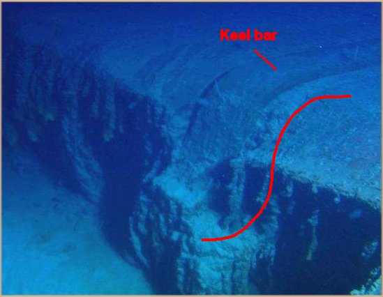
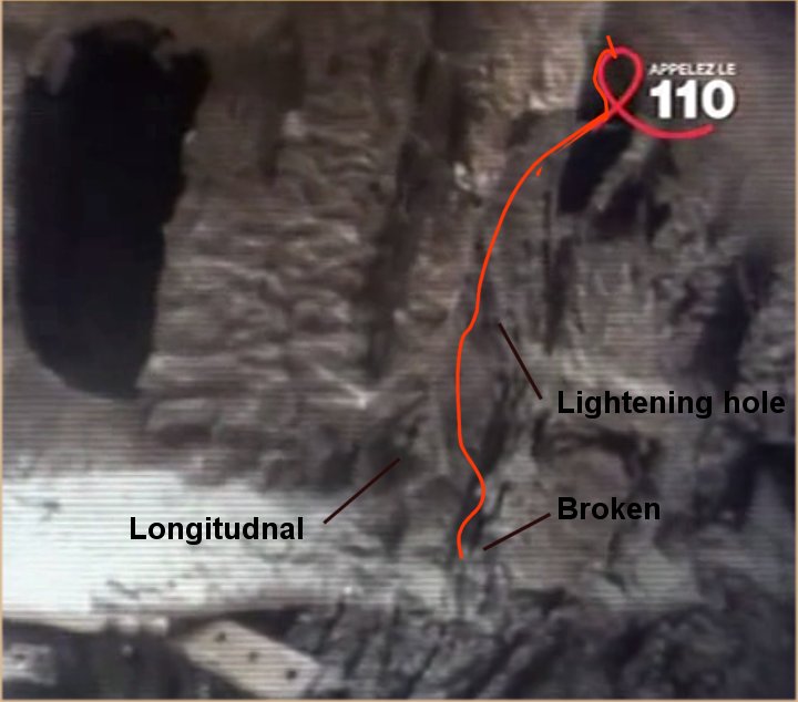
What the physical evidence shows is multi-fold. The technical artist Ken Marschall mapped the complete video into a detailed drawing based on the construction plans to identify the exact locations on the hull where the breaks occurred. Richard Woytowich, a materials science professor at New York City Technical College and co-author of the paper "The Break-up of Titanic" called the image of the bent keel bar into an S-shape the "smoking gun". The 19.5 X 3 inch (49.5cm X 7.6cm) steel bar could only be bent into that sort of shape under severe compression. That, and the frequent bent-in edges all over both sections, rule out the keel being pulled apart under tension in any 'drag the the stern' down scenario. Further evidence is in the remaining longitudal spacers found along the sections as seen in several TV programs. They appear crushed and smashed from the buckling of the double bottom.
There is also some evidence of tension breaks (being bent and pulled apart) in the outer breaks of the two keel section. That would be expected if the center collapsed and the two sections were forced inward by hydrostatic pressure and the nature of the break.
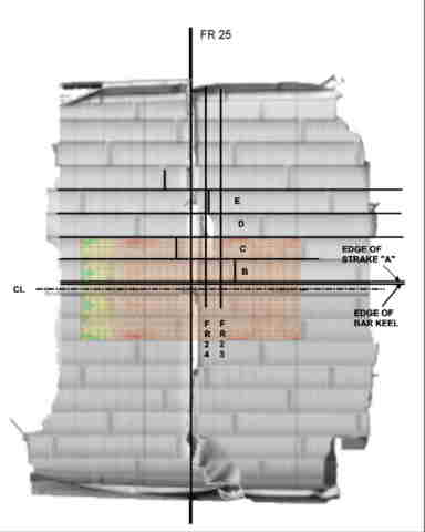
A closer look at the construction plans based on the mapping of the keel sections showed that the center of the break is at Frame 25 aft. (Frame numbers were used on all Harland & Wolff plans to precisely locate everything.) At that location, there is a difference in the overall structure of the double bottom. The thickness of the keel increases from 63 to 75 inches (160 to 190 cm), to accommodate the heavier bracing under the engines, and the change in thickness begins exactly at Frame 25 aft. To naval architects, a change in a linear stress bearing member is called a discontinuity.
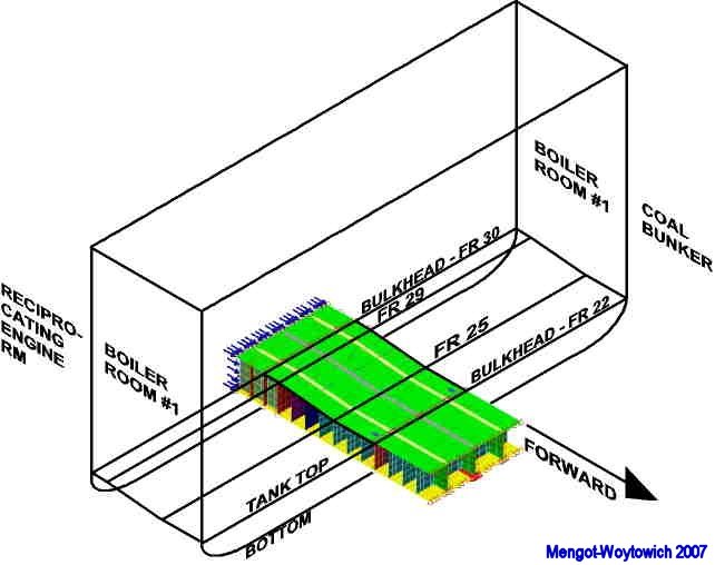
The Mengot/Woytowich paper "The Break-up of Titanic" contains detailed simulations of the structural double bottom with the ramp up to the thicker double bottom. The discontinuity in the double bottom "lights up" when subjected to the kinds of compression stress to which Titanic was subjected. The actual failure point may have been the keel bar or either of the two keelsons at the outer edges. In any event, if one goes, all three points cascade to failure almost instantaneously. It should be noted that this discontinuity in the double bottom would never pose a problem under the stresses of normal service in the North Atlantic. The peculiar predicament of Titanic tipped up like that provided the fatal conditions.
The keel broke first and the sides broke last. To understand how this could be, we look again at how Titanic was constructed. Harland & Wolff elected to have a very lightweight superstructure above the strength deck (B Deck) to allow for large palatial rooms that White Star Line owner J. Bruce Ismay wanted, without heavy bracing so high up on the ship.
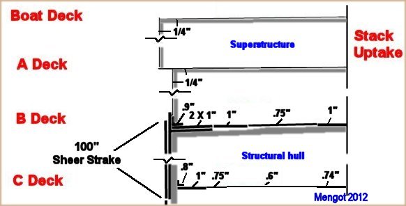
B Deck was the strength deck and was designed to withstand tension stress in concert with the top two strakes of shell plating. The top two strakes of shell plate were double 1" plates making up the top 100 inches (2.5 meters) of the sides up to B-deck. Together these are called the sheer strake. Double 1 inch plates at the outer edge of B Deck were joined to the sides by another 1 inch L-beam. B-deck then tapers to 3/4" (19mm), with a 1" (25.4mm) plate down each side of the stack uptake. The Boat Deck, A Deck and the superstructure sides were just 1/4" (6mm) plates attached to the structural hull such that heavy stresses in the hull are not passed on to the superstructure as well. A Finite Element Stress Analysis computer model must have the features adequately described to provide useful results.
Survivors testified that the stern righted itself momentarily and then tipped back up, hung there, and slipped under after a few minutes. The sequence of events must conform to that scenario and leave the wreck looking as we see it today. The break-up process is shown here as successive conditions.
The combination of the sheer strake and strength deck was much stronger under tension stress than the double bottom was in compression stress. Under compression stress, the steel doesn't have to break, it only has to bend. As soon as it starts to bend, all structural integrity is lost and it fails entirely.
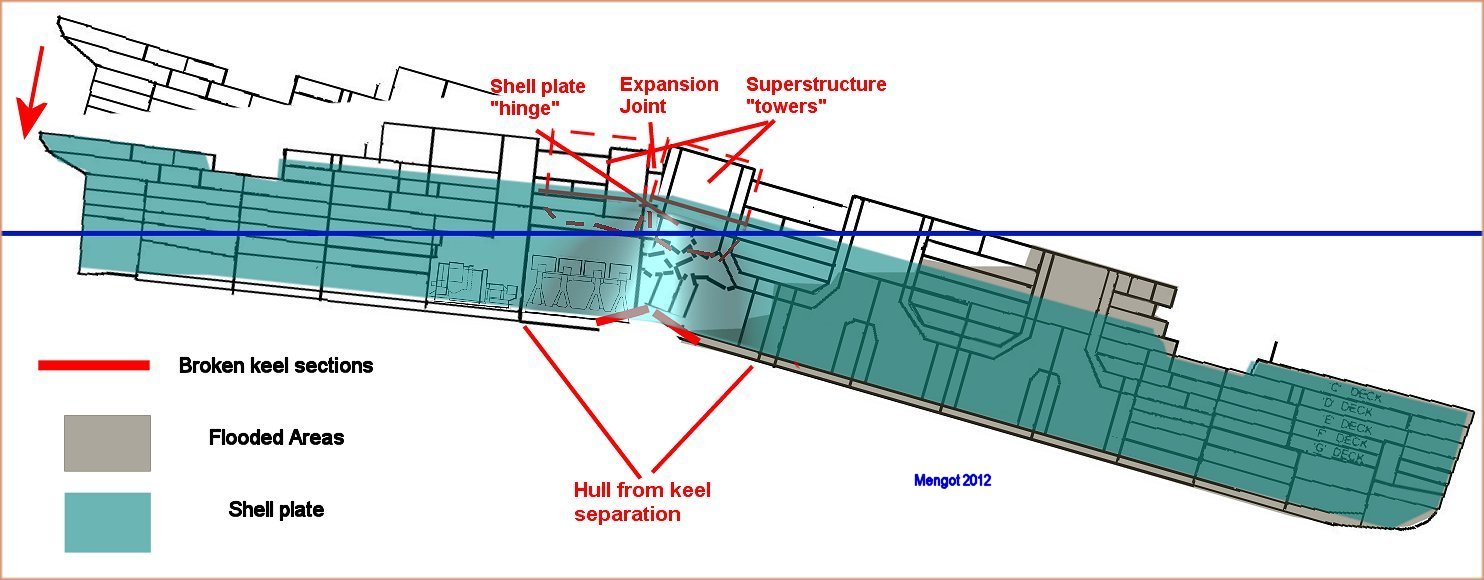
At the point where the keel fails (Condition 1), the double bottom suddenly gets shorter than the sides. The two forward cylinders of the engine, the watertight bulkhead between the engine room and boiler room 1, and the boilers are heaved violently upward. Near the keel, the sides are forced to bow or bulge outward (indicated by lighter colors in the shell plate). Since the decks can't stretch, the shell plate separates from the decks over a wide area below B-deck. The strength deck (B-deck) is the only deck continuously riveted to the sheer strake. Decks below that are not continuously riveted, but rather are attached by brackets at each rib, every 3 feet (90cm), and these brackets failed. The sheer strake (the top part of the shaded area) begins to form a hinge as the stern drops back to the water.
The separation of the shell plate from the decks occurred very commonly. Some 90% of shell plate separated from the stern section, about 20% on the bow, and all of the bow tear area. The shell plate also tears off the double bottom at the "K-strake". Each strake was lettered A to Z, and the "K strake" was the plating strake that just overlaps the top edge of the double bottom and continued upward. We ultimately see that the K-strake tear happen on both sides from the #2 boiler room in the bow to the aft end of the generator compartment, a distance of 300 feet (90 meters).
The next step has to separate the bow from the stern, but has to sink the stern as well. It can't be left as a viable boat. Condition 2 in the next figure shows how the stern tipped up and was damaged enough to cause it to sink in just a few minutes.
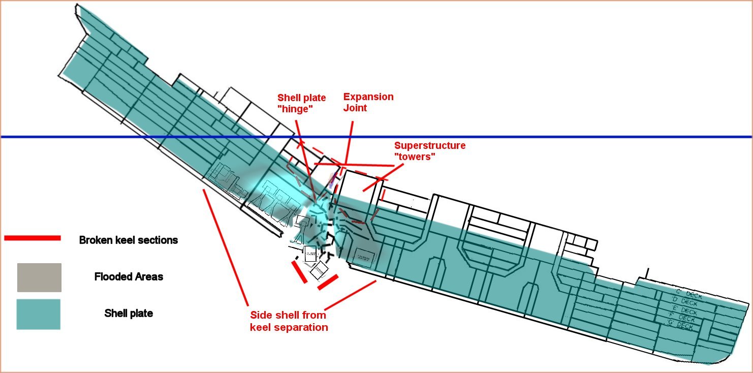
As the bow steadily drops, B-deck and heavy sheer strake stay connected
to the stern momentarily. The stern now arches back to a tipped position.
Most of the articles in the broken keel area spill out. Now B-deck has bent,
but maintains its original length. The lower edge of the shell plate suddenly
has a longer radius from the "hinge" area to traverse but it doesn't
stretch either. It bows or bulges out more and separates farther down the
keel at the K-stake to try and retain it's original length. This opens the
turbine room and even the generator compartment to the sea. Ultimately,
the shell plate has to tear into pieces from the bottom up. At this point
the shell plate has separated over such a wide area of the stern that large
sections fall off and the entire front half of the stern floods rapidly
and sinks minutes later. It is also probable that the port and starboard
sides broke at slightly different times. This asymmetric breaking of the
sides would cause the differences in how the stern appears today. Since
the ship was listing slightly to port, the stern might have a tendency to
rotate slightly to starboard while the bow, powered only gravity, tends
to move slightly to port. This would set up a twisting motion in any remaining
hull section plates still connected.
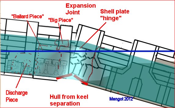
Since nearly all of the break-up happens below the surface, how do we know this "hinge" thing actually formed? The K-strake damage along the keel and the large hull sections that would be expected from this scenario are circumstantial. A key piece of physical evidence is the "Big Piece" recovered from the debris field by RMS Titanic Inc. in 1997. Two pieces of the hull located in the debris are the "Big Piece" and another piece is pictured on a National Geographic website about Dr. Robert Ballard so we'll refer to it as the "Ballard Piece." It has no name I'm aware of.
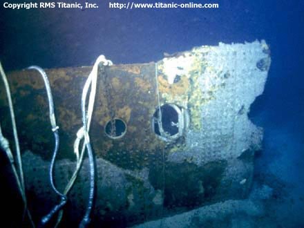
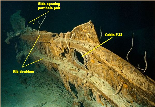
The "Big Piece" is actually quite small at some 25 feet (6 meters) wide and is from the sheer strake just aft of the expansion joint on the starboard side. The full size of the "Ballard Piece" can't be determined from this one drawing but is rumored to be fairly large and it's location can be determined by the side-opening double port holes, found only in the galley area, and the rib doublers found only at frames 47 and 48 aft in the tear area. The center port hole in the photo opened to cabin E-74 and the double port holes were in the scullery area of the galley. That makes it a large hull section that covered the starboard side of the engine room. Their story can be told by mapping them to the break-up in Condition 1 below. Also outlined is the section mentioned on the 2012 NatGeo TV show "Titanic at 100" the was found south of the stern and contained the condenser discharge pumps. That would be the next hull section back from the "Ballard Piece" and will likely map out to be starboard side of the Turbine Room.
The "Big Piece" is significant because it's part of the sheer strake and was formed by tearing the double 1" steel hull plates on each side. A simple bending force on the hull might cause the sheer strake to tear on one side, but tearing it again so nearby requires a mystery force. The only way steel plates can be torn on multiple lines like that is if there was a twisting motion on the steel. The tears may possibly have come from the top and bottom on opposite sides in that case. The "Ballard Piece" represents yet another tear in close proximity to the two tears forming the big piece. Had a clean, simple tear occurred in the shell plate, these pieces might well have been part of some of the other larger hull sections identified in the debris field. The bending, twisting, and tearing of the hull plates into smaller pieces indicates the "hinge" existed long enough to support extensive tearing of the hull laterally along the K-strake.
Additional circumstantial evidence that the sides held together for at least a short time is testimony that the stern rotated half way around before its final plunge. A tug from an uneven break by the two hull sides could induce a spin. Such a spin inducing force is lost if both sides tear top-down before the keel breaks.
Implosion and other damage
Much of the damage to the stern section is attributed to implosion damage. Implosion means that the external pressure of the water overcomes the internal air pressure and structures collapse inward.
This is easy to do in the sea. For every 32 feet of depth, sea water exerts on additional atmosphere (15 pounds per square inch) of pressure. What this means is that as the poop deck was about 1/3 submerged, the center of the after well deck was over 60 feet (20 meters) underwater, with a pressure of 2 atmospheres. That's 30 pounds per square inch or more than 2 tons per square foot. If the ship is air filled, then the decks are crushed inward by the weight of the water.
This also means that the ship was suffering implosion damage in the middle of the stern section before the poop deck was fully submerged. This would have added to the rumbling sound heard by survivors. Big ships die a horribly noisy death. Sonar operators report these noises often in wartime when a ship sinks nearby.
Remarkably, the damage to the forward half of the stern section was caused during the break-up, by rapid flooding that followed, and the final impact. It was not implosion damage. True implosion damage is surprising limited to the well deck area and the starboard edges of D, E, and F-decks. This supports the theory that stern sank listing to the port side. If compartments on a ship are already flooded, there can be no implosion.
The interior cabins are another story. As the near vertical stern sank, water raced up the decks, bulldozing the interior walls. In the areas of the cargo hatches, the water blasted down the shafts and stairs, smashing the lightweight structures between the decks. In the 1996 Angus photo view down the #6 cargo hatch, a large amount of random interior wall plating can be seen strewn about the edges of the shaft for several decks. ROV drivers have been reluctant to even try to enter the stern anywhere because a great deal of pipes and wiring are hanging about and the nature of the wreckage is a threat to the ROV tether.
The safes to the assistant purser's office were found in the debris field. They found their way out of the ship from 3 decks within and moved through 3 rows of cabins to find their exit to the seafloor.
The poop deck was peeled up either because water scooped under it during sinking or due to a final blast of air forced out from the lower decks by rapid flooding. The latter effect can often be seen in footage of cargo ships sunk by U-boats (a final geyser of water blasts out of the last cargo hatch just before the ship sinks). The poop deck peeled up as far as the aft end of the 3rd class public rooms and folded back on itself, skewed a bit to starboard. The docking bridge juts out from under the folded poop deck in the broken starboard aft corner. At least one of the forward cranes was thrown off the stern some 50 feet (15 meters) aft of the final resting place on impact.
The stern impacted rudder first, steeply enough so that the momentum of the falling stern forced it to partially collapse to form the 10 degree starboard bend under the 2nd class entrance. The poop deck was already tilted up and probably back, but the wreck shows A and B-decks around the mast tilted slightly to fore and a little to port, hence the mast is tilted slightly fore and to port. The mast will point in the direction that A-deck last shifted.
The center propeller is totally buried. The outboard props and the 'wings' to the propeller shafts were sheared from the ship and are bent upward at nearly 20 degrees, leaving the props visible almost at the level of the G-deck portholes. The starboard prop blade still sports the '401' hull number for Titanic from Harland & Wolff.
Conclusion
A top-down break requires a number of single point failures working together and plays into the strength of the ship's design. A bottom-up break works against the strengths of the ship's design. A top-down break should have left the stern afloat longer, and the front of the stern should appear more as the rear of the bow section appears today. That is not the case. A bottom-up break is more likely to leave the stern of the ship looking as it was discovered in 1985. The keel failure was then followed by cascading failures in the sides and strength deck, possibly with a twisting motion between the bow and stern, to form the pieces that have been found to date. A top-down break takes away the "energy engine" required to separate the sides from the decks and tear them to pieces. Major structures of the ship would not 'flake off' during the descent in the water column.
We still need to map the sides to fully tell the story
of the break-up but the main points of the scenario include:
The Forward Tower, Coal Bunkers, Galley Deck Section, and Forward Tower
all moved as a unit, like a giant steel post. There's a tremendous amount
of vertical steel there that is not apparent unless you go to the construction
plans and see it all lined up. In the process of bending down and then up,
it's going to crack on each side of this tower. The only question is where?
The doubling in the decks guided the cracks to 6 feet (2m) behind the funnel
uptake in the front.
The superstructure deckhouses do add a small amount of stiffening to the
strength deck so that guided the cracks behind this tower to the area along
the expansion joint.
Something on the portside shell plate held on to the smaller aft tower.
Those doublers around the uptakes may have guided a crack down the starboard
side of that uptake.
Overall, in the 15-20 second break-up process, there was a mix of bottom-up
and top-down. The initial break was apparently at the keel.
We can't rule out yet that the movement of the whole center
tower caused simultaneous cracks around the front of the #3 funnel uptake.
The uniform "knife like" break at the back of bow then occurred
as cracks radiated outward from the uptake doublers, rather than any side-to-side
cracking from the shell plate.
Further proof may lie in a full examination of the hull sections in the debris field. A consistent pattern of how the initial break propagated through the ship's structure may be found in a full mapping of the hull plates to the two uptake "towers" and internal deck sections that have now been located. I hope to look at the 2010 evidence sometime in the future.
Copyright 1997 and 2012 Roy Mengot